
 +86-18750595100


Copyright © 2025 Fujian Xinyun Machinery Development Co.,Ltd. All rights reserved. Site Map


Time: 2024-04-10
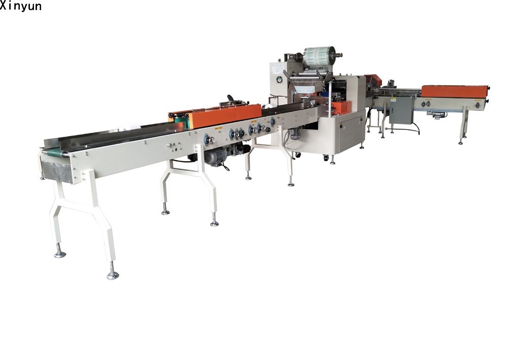
XY-503IZ Automatic Roll Paper wrapping machine
Operation and Maintenance Manual
Contents
1 Basic information of equipment..........................................................................
1.1 Application.......................................................................................................
1.2 Main specification and technical parameters.................................................. .
2 Notices................................................................................................................
2.1 Unpacking inspection.................................................................................. …
2.2 Porterage and installation.................................................................................
3 Overview of equipment function........................................................................
3.1 Performance features of equipment..................................................................
3.2 Performance features of standard material conveyor tail frame ......................
3.3 Performance features of side sealing unit.................................. ……………..
4 Installation and debugging..................................................................................
4.1 Equipment installation......................................................................................
4.2 Power supply....................................................................................................
4.3 Test running.....................................................................................................
4.4 Notices for usage and adjustment...................................................................
4.5 Parameter setup................................................................................................
4.6 Parameter instruction........................................................................ ………...
5 Equipment maintenance and inspection.............................................. ………..
6 Trouble shooting and notices..............................................................................
7 XY-503IZ Electrical drawing...........................................................................
Safety Notice for Operation on this Equipment |
※Check if there are any tools or sundries on the working table, conveying belt and sealing knife holder and no abnormality around the equipment before open equipment;
※Check that the protection device is at working station and set the speed 30 packages/min in the touch screen before open equipment.
※Forbid any part of the body approaching to or touching the operation part during equipment operation.
※Forbid hands and tools driving into the knife sealing holder during equipment operation.
※Forbid switching the operation button frequently and change the parameter settings at random when the equipment is in normal operation.
※Forbid more than two persons to operate kinds of switch buttons and mechanisms of the equipment at the same time, close the power when maintaining and repairing, and keep communication and indication to avoid any accident caused by non-coordination when many persons operating the equipment.
※Forbid hot line work when checking and repairing the electric control circuit! It must finish it by electric professionals. The machine program is automatic locked and can not be changed without authorization.
※When an operator can not keep sober due to drinking or fatigue, forbid operation, debugging or repairing equipment. Other non-trained or unqualified persons should not operate equipment.
※Forbid changing equipment without our permission and don’t use the equipment under the non-specified condition.
※The insulation resistance and ground resistance comply with the national safety standard when leave factory. If this equipment has not been used for a long period or for the first time use, the heater should be heated about 20 min in low temperature avoiding humidity in the heating part of this equipment.
Warning! For the safety of you, others and equipment, please operate according to the above requirements. We assume no obligation for any accident due to breaching above requirements
|
1.Basic information of equipment |
1.1 Application
※This equipment is applicable to package of the roll toilet paper ball with the core within the scope of various specifications.
※This equipment has the features of compact package and smooth side sealing;
※Easy and flexible operation;
※Quick operation, stable and low-noise and other features.
1.2 Main specification and technical parameters
Machine model | TP-R220M |
Packing speed | 40-200 rolls/min |
Max. width of packaging film | 430mm |
Roll paper diameter | 80-130mm |
Roll paper length | 90-150mm |
Motor power | 3.2KW |
Total power | 12KW |
Machine net weight | 1800KG |
Machine noise | ≤80 Decibel |
Qualification rate of production | ≥97% |
Machine dimension | 5500x3300x1600 |
Power supply | 380V,50HZ |
Packaging material | SPP,BOPP,CPP etc. |
Film thickness | 0.018-0.035mm |
2.Notices |
2.1 Unpacking check
☆ Notice
After received the packing equipment, should checked as follows:
Check if the product model is consistent with the booking goods.
Check if the fittings of the packer are complete.
Check if the goods is damaged in transportation.
2.2 Porterage and installation
☆ Notice
Please put down gently for the packer when moving, avoid any damage..
Please hold up the bottom of the packer when moving. Otherwise, it may lead to damage by
falling onto the ground.
Do not install a damaged or without protection machine, which has personal injury and
damage danger.
Machine can be moved and installed after the power was cut off.
3. Overview of equipment function |
3.1 Performance features of main equipment
1.The usage of main control circuit is motion controller that reached & developed by us independently.
2.The nucleus part is controlled by servo which is high
precise.
3.The human-machine control interface, quick and convenient.
4.Advanced electronic cam knife, speed adjustable, no need for manual regulation .
5.Use intelligent temperature control separately, each sealing mouth accurate.
6 .Tracking system is adopted high-precision photoelectric.
7.Advanced empty package prevention technology, no material and no packing, avoiding packing film loss.
8 .Use special fixed former
9 .The finished products are beautiful and the sealing is level.
3.2 Performance features of standard material conveyor tail frame.
1.The material conveyor tail frame is connected with the main machine that is full automatic feeding system.
2.The material conveyor is controlled by servo motor which is high precision.
3.High precision electronic eye detection is more accurate.
4.The part contacts the paper roll is made of materials meet the national health standard.
5.The design, each diameter are adjustable and convenient.
3.3 Performance features of side sealing unit
1.The rolling and side sealing unit are adopted patented technology, the packing effect is more beautiful.
2.Adjustment is easy and the side sealing is more level.
4. Installation and debugging |
4.1 Equipment installation
4.1.1The equipment should be installed on the level ground, referring to the convey
level of the products for horizontal installing the equipment. For level installation, please place a horizontal instrument for reference, adjust four ground bolt screws under the equipment for horizontal installation. If the equipment need to be connected with other equipment, assured the height of conveying level and then adjust it.
4.1.2 Do not install the equipment at the following sites. otherwise, it may affect normal operation of equipment.
4.1.3 Non-horizontal position.
4.1.4 Direct sunshine site:
※If the equipment is installed at the site with direct sunlight or strong sunlight, the photoelectric switch will be not work.
4.1.5 The place where too low or high temperature and the space is too narrow:
※The proper operation environmental temperature of this equipment is 0~45℃. Humidity: no condensation water.
4.1.6 Not in the site with a vibration source.
4.1.7 The equipment should be near the area that air outlet of ventilation equipment and air conditioner.
4.1.8 Severe environment with erosive gas or dust are not suitable for usage and maintenance of equipment.
4.2 Power supply
4.2.1 Connect power supply:
Connect the power cable to the air (current leakage) switch that matched with the equipment power.
Notice: This equipment power is 220V 50Hz AC. It is forbidden connecting this equipment to 380V AC or other power supplies which are not comply with the above power requirements. For safety, electric professionals are required for connection, the equipment should be grounded.
4.2.2 Turn on the general power switch on the right side of the electric box.
4.2.3 Turn on the power switch and temperature control switch (the temperature 1600C).
4.3 Test running
4.3.1 After the power is connected at the first time,
operation steps as follows:
The operation button panel is located at the front of the sealing knife unit and
including“Emergency stop”, “Recycling stop”, “Start” and “joggle” button.

4.3.2 Open the temperature control panel, set the
temperature as 100, the speed in the touch screen as 40, color code/length-fixed button as the fixed length, and press ‘Start’ button, the equipment will automatically start after automatic initialization. Press the ‘recycling stop’ button after the knife sealing rotates to one circle. Press ‘joggle’ button, after the equipment stopped, and check if there is abnormal sound and blocking during operation. If any abnormal occurs, immediately stop operation, eliminate the failure and then restart the equipment.
4.3.3 Press ‘Start’ button after made sure no abnormality, rotated for several rounds, adjust the speed in the touch screen to 50 and continue running the equipment. After 5 minutes, adjust the speed to 100 and continue operation.
4.3.4)Observe the statement of temperature control module, adjust the middle sealing to 125℃ after the temperature reached the setting one or higher than the setting, and keep side seal temperature. After the temperature stable at the set temperature, press ‘stop’ button stop this equipment.
4.3.5 Adjust the speed as 30, set the bag length and the packing film
number same as the color code distance’s, and put the packing film according to the
‘schematic diagram of the film crossing’ and via the ‘bag former’ till ‘knife sealing
unit’. Close the paper pulling unit of the middle seal, adjust the tension of the film via
the tension adjustment swing pole, close the rubber roller, and press ‘joggle’ button. At this time, the packing film should smooth pass. If not then adjust the ‘tension
adjustment swing pole’ or adjust front and the back of the bag former till the packing
film smooth passes. Place the color code detection electronic eye on the color code
point of the packing film, and change the ‘color code/length-fixed’ button in the touch
screen change to the color code. Start the equipment, the equipment will automatic
track and observe the cutting position of the knife edge, the ‘adjust button’ on cutting
position in the touch screen will cut the needed position (generally it is located at the
color code). stop equipment after adjustment.

4.3.6 Take one paper ball, adjust the belt width of the material conveyor tail frame make it suitable to paper roll diameter (to just clamp the paper roll), and adjust the width of the feeding damper, it is about 3mm longer than the diameter of the paper roll. Notice: the center of two damper should correspond to the center of the bag former.
4.3.7 Put a paper ball at the empty position between the push rod, jog the equipment, and check if the material position is accurate by observing the position of the paper ball and packing film pattern (the paper roll should be overlapped with the pattern of the packing film). If they are not accurate, take out this paper ball, adjust it via adjustment button in material position -+-- the touch screen, and repeat the above action till the material position is accurate. Adjust the width of the output damper of the main machine (the method and requirement are same as feeding damper) and adjust the brush (to just press the paper ball).

4.3.8 Take one paper roll, adjust the damper width of the sealing unit (the method and requirement are same as feeding damper), rotate the paper roll to 90℃, adjust the height of press and feeding unit of up twisting bag position according to the diameter of the paper roll (to just press the paper roll), adjust the width between the cutting plate of the twisting bag device according to the size between the planes at two ends of the paper roll ( bigger about 8mm than the paper roll ), and adjust the gap of the cutting plate according to the diameter of the paper roll, and adjust the width of the thermal sealing pressing belt according to the gap between the planes at two ends of the paper roll (to just press the paper roll ).

4.3.9 Press ‘Start’ button of the side ironing mechanism, and check if the machine is exceptional (Notice: it may lead to friction between the cutting plate and belt when adjusting, please note). If no exception occurs, continue operation.
4.3.10 Set the function of the empty package prevention in the main machine
touch screen, set the linked action /single action button as linked action, adjust the
detection electronic eye to the function status, and press Start button, the equipment will enter the production operation status. at this time, place the product package.
4.4 Notices for operation and adjustment
4.4.1 General information on whole TP-R200SD machine:
The TP-R200SD single rolled paper packer consists of automatic feeding tail bracket, main machine, material output tail frame and side sealing tail frame.

General information on debugging in production:
4.4..3 Install the packing film on the paper support roller, feed out the film, and pull in the anticlockwise direction.
4.4.4)The paper film moves in the following direction. If the equipment is installed with the coding machine, please first make the packing film bypass no-film stop roller, tighten the swing roller and roller of the coding machine, and enter the active film feeding roller from the up surface of the electronic eye reflection plate. When the packing film bypasses the active feeding roller, turn the open/close handle of the film feeding roller, separate the active film feeding roller and rubber roller, and drill the paper, finally make the paper film bypass the angle rocker roller of the bag former, and enter the bag former. then open the open/close handle of the sealing paper feeding wheel in the equipment, make the paper drill through the paper feeding wheel and press wheel, close the open/close handle of the paper feeding roller and wheel in turn, continuously press joggle button, and make the packing film drill through the sealing knife holder. At this time, the paper installation step ends.

Notice: there is a micro switch under the no-film stop roller. When no film of paper roll
passes this switch, the machine will automatic stop avoid second film crossing and save
the packing film.
4.4.5 Adjustment of paper film tension:
Rotate the angle rocker adjustment handle to keep tension of three edges of the packing film of the bag former similar. If the accumulated film or pull film exists between the active film feeding roller and paper feeding wheel, it can be adjusted by adjusting the speed micro handle wheel of the film feeding roller.
If no accumulated film or pull film exists between the paper feeding wheel and press
wheel, it can be adjusted by adjusting the speed micro handle wheel of the press wheel.If two edges of the middle seal are not aligned, it can be adjusted via the center
alignment adjustment handle wheel of the rolling film.
4.4.6 Stop running after the packing film smoothly passed the equipment and met the requirement via the above steps.
4.4.7 To turn on the color code function button on the touch screen, place the color code detection electronic eye on the color code trace of the packing film, and start the equipment, the equipment will enter automatic tracking status. at this time, check if the cutting position is at the middle of the transparent area between two patterns and adjust it via the cutting position button on the touch screen.
4.4.8 After the above steps are completed, take a packed object, adjust the width of the feed baffle plate, and place it at the middle of the pull pole of the feeding tail bracket, joggle equipment, check if the packed object is located at the middle of the packing film pattern, and adjust it via the material position on the touch screen.
4.4.9 Adjust the height of the blade center of the traverse seal according to
the height of the packed object and make it high as the center of the packed object. The
height adjustment method of the traverse seal mechanism is shown as follows: first
loosen two M8 hexagonal screws on the right guide of the knife seal frame, open the
protection cover door of the drive mechanism, manually rotate the end sealing
mechanism to make the adjustment wheel ascend/descend, and keep the height of the
matching center of the knife base be consistent with it of the packed products. After
adjustment, make sure to tighten the loose two M8 hexagonal screws and start the
equipment.
4.4.10 After the above steps are completed, adjust the width between the clamping belts of the
material arrangement trail rack. After adjustment, set the linked operation/single
operation button on the touch screen as linked operation function, enable the empty
package prevention function, start the equipment, and enter the production mode.
4.4.11 The traverse sealing knife base and cutter are shown as follows:

4.4.12 Adjustment of traverse seal knife base
Adjustment quality of the knife base will determine the quality of the end seal. The knife base of this equipment is designed as dull knife and is carefully adjusted and strictly tested at the factory. For adjustment, clamp the carbon paper between two white paper and check if the press texture is same
at two ends. If they are different, adjust it via the adjustment screw of the knife base.
check if it is in mal position.

※If two knife bases are not dislocation badly, slightly loosen two M10
screws and reinforcement screw of the up knife base or down knife base, and adjust two M5 socket head cap screw above the M10 screw (first loosen the lock bolt of M5 screw) till ideal position. Finally lock the lock nut of the M5 screw, lock M10 screw and reinforced screw.
※If two knife bases are in worse dislocation , first loosen M10 screw of the pivot point shaft of the fixing swing arm (do not fully separate) and then slightly strike two M6 screws on the pivot shaft of the swing arm (left or right) till ideal position. Finally
tighten M10 screw. When the knife base is in worse dislocation, it is possible to perform above adjustment in two steps simultaneously.
※The above adjust for knife bases must without heating.
4.4.13 Adjustment of cutter
When the cutter does not cut off the paper film, it should be adjusted as follows: loosen the lock nut of the M6 cutter adjustment screw on the knife base and tightening screw of the fixing cutter, and adjust the cutter adjustment screw by adjusting from outside to middle, shown as the figure. keep the consistent force, first cut off the paper film, and keep no impact force of the up and down cutter. If it can not be adjusted for proper position, replace it with a new cutter. adjust the cutter under heated status (about under 90℃).
※After the cutter is adjusted, make sure to tighten the lock nut of the adjustment screw and cutting fixing screw.

4.4.14 Adjustment of bag former
The bag former is located on the left of the machine table and shapes the packing film
here. The traverse position and longitudinal position to the middle seal paper feeding
wheel can be adjusted. The adjustment effect of the bag former will directly affect bag
making quality, so it should strictly comply with the following requirement in
adjustment of the bag former.

4.4.15. Adjust center line position of the bag former: the center line of the bag former should be overlapped with the center line of the center seal. If they are not overlapped, it should be adjusted as follows: loosen M12 lock nut and M8 screw. If the center line of the bag former deviates inward, rotate the adjustment screw of the bag former in anticlockwise. On the contrary, adjust it in the clockwise direction. repeatedly adjust it till the center line of the bag former is overlapped with the center line of the middle seal and finally M8 screw and M12 lock nut are locked.
Notice: three bag make adjustment screw should be adjusted in a synchronized manner.

4.4.16. Height adjustment of bag former: the bottom plane of the side plate of the bag former should be overlapped with the up surface of the middle seal panel. The bag former will not press on the middle seal table panel and no gap is reserved. The adjustment method is described as follows: loosen M8 screw and M6 adjustment bolt on the adjustment screw of the bag former, and slightly move the bag former up and down till the above requirement is met. Finally tighten M6 adjustment bolt and M8 screw.
4.4.17. Adjustment of adjustment side wing plate of bag former: when the tension of the packing film is not uniform, the side wing plate of the bag former should be adjusted. The tension of the packing film is adjusted by changing the opening angle of the side wing plate. The adjustment method is described as follows: loosen the screw, adjust the side wing plate angle of the bag former till the required tension, and tighten the screw.
This process should be repeated multiple times till proper tension.
4.5. User parameter setup
4.5.1 Main menu
To enter the homepage, the touch screen is displayed as follows

clicking any number window of speed, packing film length, side sealing speed feed out speed, material position, cut-off position material conveyor position will pop up the digital input window.
The line connection switch is connecting with the medium-size packer to control the line
 The above indication of digital window can input maximum & minimum value
 ![]() Clear button, can clear the input number.
Clear button, can clear the input number. ![]() Exit button, can exit from current input.
Exit button, can exit from current input.![]() Enter button, can confirm the input number.
Enter button, can confirm the input number.
Speed: set the operation speed
Packing film length: Set the length of the packing film.
Tracking mode: it includes the fixed length and color code, set according to actual condition.
Operation mode: it is divided into single operation and linked operation. If single operation
is selected, the material conveyor will not work. If linked operation is selected, the material conveyor will operate with the packer.
Notice: to switch the operation mode, should stop equipment .
Empty package function: it is used to enable or disable the empty package
detection. When the empty package function open and no material passing, the empty package
detection electronic eye make the cutter and film feeding unit will not work.
Discharging speed: it is used to set the discharging speed.
Side sealing speed and side sealing switch: Set the side sealing speed and if you use side sealing.
Notice:
Operate the machine, the side ironing function must open. If close it when running, the machine will stop.
Material position, cut-off position and material conveyor position: They are only used as reference for shift direction of film and paper.
4.5.2Parameter setup page
Click Menu![]() ->User parameter, enter the user parameter setup interface.
->User parameter, enter the user parameter setup interface.

The menu can set the knife speed proportion, synchronization range, tearing mouth position, material length, cycle stop position, material plug frequency, discharging speed, discharging alarm time and code marking position. Click each digital window, the number input window will display to set the user parameters.
To press ![]() Next page, a user can skip to the second page menu of the user parameters, shown as follows:
Next page, a user can skip to the second page menu of the user parameters, shown as follows:

The menu can set learning and Forbidden of control for cutting material prevention , tolerant length of cutting material, number of empty packages, color code range, failure time of color code, and discharging alarm time.
Press Previous page, a user can return the first page of the user parameter.
4.5.3 Manual control page
Click Menu-> Manual operation, ause can enter the manual control page.

Privilege selection: to input the main machine parameter page password, a user can enter the machine parameter setup.


1. Guarantee that the rail frame coder and each zero clearing switch of shaft can normally work.
2. The maximal output frequency of the frequency converter is corresponded to the set maximal frequency and one round pulse number for cutter servo
3. Set the joggle operation frequency for the cutter shaft and paper feeding shaft, set 20HZ for self check frequency and press self check, start the machine. After self checked and the machine stopped, the transmission parameters of each shaft will be automatically calculated.
The parameters on the touch screenshot is only for reference.
Main machine user can set the tail frame parameter, cutter parameter, paper feeding parameter, speed parameter and self check parameter.
Tail bracket parameter: this page can set the tail bracket gap and tail bracket rotation number and
can display zero clearing phase of the tail bracket, tail bracket phase and speed.
Cutter parameter: this parameter can set the cutter precision, cutter perimeter, cutter correction, gain, joggle frequency and original point frequency and can display the zero clearing phase of the cutter.
Paper feeding parameter: the page can set the paper feeding precision, paper roller
perimeter, gain, joggle frequency, and original point frequency and display the zero clearing phase of paper feeding.
Speed parameter: This page can set the acceleration time, maximal output frequency and main machine transmission ratio.
For parameter details, refer to the parameter instruction.
4.5.5 Material arrange parameter setup page
Click Menu-> Material conveyor parameter button, a user can
enter the material conveyor (manufacturer) parameter setup. Notice: non technician should not
change it to avoid influence normal operation


The first page for material arrangement can set the leather belt diameter, transmission ratio, pole pair and conversion frequency of the page 1 and 2.
The second page for material arrangement can set gain, restriction percent, DA gain rate, acceleration percent, section distance, material conveyor spiral coder line number, service motor line number, packing stop time, packing start delay and acceleration ratio.
4.5.6 Temperature setup page
To click Menu ->Temperature button, a user can enter the temperature control page.

On the temperature control page, a user can view actual temperature of the middle seal 1, middle seal 2, traverse seal 1, traverse seal 2, side ironing 1 and side sealing and set the temperature of the middle seal 1, middle seal 2, traverse seal 1, traverse seal 2, side ironing 1 and side ironing 2. A user can set the temperature control
start/stop of middle seal 1, middle seal 2, traverse seal 1, traverse seal 2, side sealing 1 and side sealing 2.
4.5.7 Monitoring page.
To click Menu ->I0 Monitor button, a user can enter the monitoring page.

The monitoring page displays input and output of MP02 control panel. X0—17 are for input and
Y0—17 are for output. The number 0 under X (Y) number indicates no signal input (output). The page also displays actual values such as current speed, actual film length and tail film angle.
4.6. User parameter instruction
4.6.1 User parameters
Pr01 speed | Factory value | 40 |
Setting range | 40-200 packs/min | |
Set current operation speed. The default is 40, namely 40 packages/min.
The range of this parameter depends on the film length and top frequency of frequency converter.
Generally the longer film length indicates lower speed.
Pr02 film length | Factory value | 40 |
Setting range | 40-999 | |
Set the length of the packing film. Unit: mm.
Pr03 side ironing speed | Factory value | 100 |
Setting range | 0-300 | |
It is used to set the motor speed of
the side ironing tail bracket when the side ironing tail bracket rotates and seals.
Pr04 material position | Factory value | 0 |
Setting range | 0-tail bracket gap | |
This parameter adjusts the relation of the cutter and paper cut-off position. Unit: mm.
Remark: The parameter setting can not exceed the gap of the tail frame Otherwise, the system will automatically handle it.
Pr05 cut-off position | Factory value | 0 |
Setting range | Film length | |
This parameter adjusts the position relation of the cutter and color code. Unit: mm.
When the value of this parameter is less than half of the paper length, the color code will forward to approach to the cutter. If it is longer than half of the paper length, the color code will back to approach to the cutter.
Remark:
The set value of this parameter should not be over the length of the packing film. If it is over packing film length, the system will automatically handle it.
Pr06 material sorting position | Factory value | 0 |
Setting range | 0-tail bracket gap | |
Adjust the entry position of the material at the tail bracket. Unit: mm.
Remark: The set value of this parameter should not be over the tail frame gap. If it is over the gap, the system will automatically handle it.
Pr07 knife speed production | Factory value | 90 |
Setting range | 10-999 | |
This parameter is used to set the synchronization speed of the cutter and pull film. Generally the cutter speed ratio is 1:1. If the film is piled in cutter, this parameter should be over 100. If the film is pulled or the film is too thick, the parameter should be less than 100.
Pr08 synchronization range | Factory value | 45 |
Setting range | 5-360 | |
This parameter is set to cut the material within same range of the cutter and material. Unit: mm
Notice: This parameter is used to set the minimal same angle range according to the knife
width.
E.g. When the knife width is 100mm and the cutter perimeter is 200mm, the paper is 200mm long.
10 / 200 = X / paper length
X = 10 Minimal synchronization angle: X=10
Remark: Generally the set value is more than minimal synchronization angle.

Pr08 bearing mouth position | Factory value | 0 |
Setting range | 10-999 | |
Exhaust position setting for tearing mouth of non-core paper
Pr09 material length | Factory value | 100 |
Setting range | 50-600 | |
Actual material length: unit: mm
Pr10 cycle stop position | Factory value | 16 |
Setting range | 0-359 | |
It indicates stop position in cycle stop of the machine.

Pr11 material plug frequency | Factory value | 0 |
Setting range | 10-999 | |
Set 90° side sealing material plug frequency
Pr12 discharging tail bracket speed | Factory value | 1000 |
Setting range | 0-9999 | |
setting of output speed and material output speed.
Pr13 output alarm time | Factory value | 1000 |
Setting range | 0-9999 | |
Set the up stuffing time of the output channel. Unit: mm.
Pr14 code making position | Factory value | 0 |
Setting range | 10-999 | |
It is used to set the code marking position of the code marker.
Pr15 code making position | Factory value | 0 |
Setting range | 0-1000 | |
Residual cutting material
Pr16 line connection start delay | Factory value | 0 |
Setting range | 0-6000 | |
For the line connection of middle packer, it is used to set delivery time of single package start signal from the middle packer. Unit: mm.
Pr17 empty package number | Factory value | 1 |
Setting range | 0-999 | |
Number of the pitches from the empty package prevention electronic eye to the material entry point of the bag former.
It is shown as follows:
Pr18 empty package deceleration | Factory value | 80 |
Setting range | 0-200 | |
It is the speed which the empty package prevention detection electronic eye will decelerate to when no material is detected.
Pr19 line connection stop delay | Factory value | 0 |
Setting range | 0-6000 | |
It is the stop delay when TP-R220M receives no material signal in line connection of the middle packer.
Pr20 color code range | Factory value | 15 |
Setting range | 1-99 | |
This parameter
is used to show the valid range of the sensor signals recognized by the color code. The
position behind and before the color code is valid. When the valid range is narrow, the color recognition signal will be canceled and an alarm will display. Unit:

Pr21 color code failure time | Factory value | 5 |
Setting range | 1-1000 | |
This parameter indicates that the color code sensor will not instantly alarm but it detect reached the set range of the color code
Pr22 acceleration time and deceleration time | Factory value | 3000 |
Setting range | 1-6000 | |
This parameter is used to set the start response time and deceleration response time of the machine. Unit: mm.
Pr23 tail bracket phase | Factory value | null |
Setting range | 0-tail bracket rotation number | |
This parameter is used to monitor the tail bracket coder counting. If this parameter does not change in operation, it indicates that the coder is damaged or the line contact is bad.
Pr24 tail bracket rotation number | Factory value | 1440 |
Setting range | 200-9999 | |
It is the resolution of the tail bracket coder: unit: P
E.g. If the coder line number is 360P, this setting is 1440 (360 * 4).
Pr25 tail bracket zero clearing phase | Factory value | null |
Setting range | Tail bracket rotation number ±10 | |
This parameter monitors if the tail bracket coder will be reset to zero at the set tail bracket spiral coder value.
If the machine is in operation, the value should be around tail frame
rotation number±. otherwise, the coder will jitter or the electronic eye of tail frame zero clearing detecting signal is disturbed. At this time, the circuit should be checked.
Pr26 tail bracket gap | Factory value | 240 |
Setting range | 0-9999 | |
Set actual pitch of the tail bracket. Unit: mm
Pr27 cutter precision | Factory value | 1000 |
Setting range | 500-65535 | |
Cutter servo resolution: unit: P
E.g. the pulse number of one servo round is 1000.
When the cutter transmission ratio is 10, this set value is 10000 (1000 * 10).
Pr28 cutter perimeter | Factory value | 594 |
Setting range | 50-1000 | |
This parameter sets the perimeter of the traverse seal. Unit: mm
E.g. When the center distance of traverse seal is Ф38.20mm:
Single knife: 38.20 * π = 120
Double knives :38.20 * π / 2 = 60
Three knives: 38.20 * π / 3 = 40
Four knives: 38.20 * π / 4 = 30
Pr29 cutter gain | Factory value | 450 |
Setting range | 0-3000 | |
It is the adjustment coefficient of the feeding paper tracking motor of the cutter motor.
Pr30 cutter original point frequency | Factory value | 3500 |
Setting range | 0-65535 | |
It is the original point signal seeking speed of the cutter original point sensor in case of booting and pressing start button. Unit: HZ.
Pr31 cutter joggle frequency | Factory value | 2000 |
Setting range | 0-65535 | |
It is the output frequency when the cutter servo motor joggles. Unit: HZ
Pr32 cutter correction | Factory value | 0 |
Setting range | 0-65535 | |
This parameter is used to adjust the precise position of the cut material.
Pr33 cutter zero clearing phase | Factory value | null |
Setting range | cutter precision ±10 | |
This parameter is used to track and monitor the cutter. the phase value of zero clearing will be updated once when the cutter rotates one round.. The updated value approaches to the set cutter precision.
Pr34 paper feeding precision | Factory value | 11200 |
Setting range | 500-65535 | |
Paper feeding service resolution: unit: P
E.g. The pulse number of one servo round is 1000.
When the paper feeding transmission ratio is 10, this value is set as
10000 (1000 * 10).
Pr35 paper roller perimeter | Factory value | 200 |
Setting range | 50-1000 | |
It is final roller shaft perimeter of the paper roller. Unit: MM
E.g. When the center distance of the paper roller is Ф63.69mm
63.69 * π = 200
Pr36 paper roller perimeter | Factory value | 800 |
Setting range | 0-3000 | |
It is the adjustment coefficient of the tracking cutter motor of the paper feeding motor.
Pr37 paper feeding original point | Factory value | 2000 |
Setting range | 0-65535 | |
It is the original signal seeking speed of the paper feeding original point sensor in case of booting and pressing Start. Unit: Hz.
Pr38 paper feeding joggle frequency | Factory value | 2000 |
Setting range | 0-65535 | |
It is the output frequency when the paper feeding motor joggles. Unit: HZ.
Pr39 paper feeding zero clearing phase | Factory value | null |
Setting range | Paper feeding precision ±10 | |
This parameter is used to track and monitor the paper feeding. , the phase value of zero clearing will be updated once when the cutter rotates one round. If the paper roller perimeter is set as the paper length, the zero clearing phase will approach to the paper feeding precision. it is valid under the color code status.
Pr40 acceleration and deceleration time | Factory value | 3000 | |
Setting range | 60-65535 | ||
Set quick or slow time of machine stop when cycle stop. Unit: MM.

Pr41 main transmission ratio | Factory value | 50 |
Setting range | 0-65535 | |
It is the final transmission ratio from the main motor to the tail bracket.
Pr42 maximal frequency | Factory value | 90 |
Setting range | 0-65535 | |
Maximum frequency set by the frequency converter. Unit: HZ.
4.6.3 Material arrangement parameter
![]()
Pr43 diameter of first leather belt | Factory value | 78 |
Setting range | 0-65535 | |
It is used to set the diameter of the leather belt 1, which is changed according to the actual value. Unit: MM
Pr44 diameter of second leather belt | Factory value | 95 |
Setting range | 0-65535 | |
It is used to set the diameter of the leather belt 2, which is changed according to the actual value. Unit: MM
Pr45 transmission ratio first leather belt | Factory value | 1000 |
Setting range | 0-65535 | |
It is a mechanical parameter and is the final transmission ratio from the first leather motor to the belt.
Pr46 second transmission ratio | Factory value | 1000 |
Setting range | 0-65535 | |
It is a mechanical parameter and is the final transmission ratio from the second leather motor to the belt.
Pr47 first conversion frequency | Factory value | 0 |
Setting range | 0-999 | |
If the first motor is driven by the frequency converter, this parameter is the maximum
frequency of the frequency converter.
If the first motor is driven by the servo, this parameter is set as 0. Unit: Hz.
Pr48 second conversion frequency | Factory value | 70 |
Setting range | 0-999 | |
It is the maximum frequency of the second motor frequency converter.
E.g. If the maximum frequency of the frequency converter is set as 90, this parameter is set as 90.Unit: Hz
Pr49 Pole pair of first motor | Factory value | 0 |
Setting range | 0-99 | |
If the first motor is driven by the frequency converter, this parameter is the pole pair of the motor.
If the first motor is driven by the servo, this parameter is set as 0.
Pr50 Pole pair of second motor | Factory value | 2 |
Setting range | 0-99 | |
It is the pole pair of the frequency conversion motor.
E.g. If the frequency conversion motor is 4-pole motor and the pole pair number is 2, this parameter is set as 2.
Pr51 Gain | Factory value | 50 |
Setting range | 0-65535 | |
It is used to adjust the tracking tail bracket position parameter of first material arrangement motor. The default is 50.
Pr52 Restriction percent | Factory value | 50 |
Setting range | 0-65535 | |
It is used to adjust the output restriction ratio of the first material arrangement motor.
Generally it is set as 50.
Pr53 Acceleration percent | Factory value | 50 |
Setting range | 0-65535 | |
It is the determination range of the first material arrangement acceleration. generally it is set as 50.
Pr54 Acceleration percent | Factory value | 50 |
Setting range | 0-65535 | |
Its value is the percent of the calculated acceleration output.
Pr55 gain | Factory value | 30 |
Setting range | 0-65535 | |
It is the compensation coefficient of the second frequency conversion motor.
Pr56 pitch | Factory value | 200 |
Setting range | 0-65535 | |
It is the tail bracket gap. Unit: MM.
E.g. If the gap of the packer tail bracket is 200mm, this parameter is set as 200.
Pr57 material arrangement spiral coder line number | Factory value | 360 |
Setting range | 0-65535 | |
It is the line number of the principal axis coder.
E.g. When the tail bracket coder of the packer includes 360 lines, this parameter is set as 360.
Pr58 line number of servo motor | Factory value | 200 |
Setting range | 0-65535 | |
It is the pulse number of one servo motor round.
E.g. If the pulse number of one servo motor round is 200, this parameter is set as 200.
Pr59 Packing start time | Factory value | 500 |
Setting range | 0-65535 | |
It is the set time for the material arrangement and packer start for linked operation. Unit: ms.
Pr60 Packing stop time | Factory value | 0 |
Setting range | 0-65535 | |
It is the set time for the material arrangement and packer stop for linked operation. Unit: ms.
Pr61 set alarm time | Factory value | 0 |
Setting range | 0-65535 | |
Reserved by the system
5. Equipment maintenance and inspection |
5.1 The equipment should be maintained and cleaned every day or shift.
5.2 Each time packing is completed, the equipment should be cleaned.
5.3 Before the machine is cleaned, cut off the power and ensure that the heating component is cool.
5.4 Do not directly spray the water or steam on the equipment in cleaning.
5.5 Main cleaning components:
※If the product scrap is accumulated on the product transportation line, it should be cleaned with the compressed air or other methods.
※If the film scrap sticks to the sealing surface of a middle seal or end seal, brush and remove it with the steel wire brusher coated by the silicon lubricant.
※Wipe off the dirties on the control panel, protection cover and table panel with a soft cloth.
※Conductive ring of knife seal and middle seal: stop and cut off the main power every other one week or two weeks and clean the conductive ring with the back of abrasive paper.
5.6 Monthly maintenance and inspection of equipment
5.6.1Add lubricating greases for the bearing of the middle seal component
5.6.2 Add lubricating grease for the gear and chain (wheel) for the transmission component.
5.6.3 Check if the chain and leather belt of the
transmission component is loose. If it is loose, the chain and belt should be tightened.
5.6.4 Check if the fastening screws or nuts
of different components are loose. If they are loose, the screws or nuts should be pressed tightly.
5.6.5 Check the equipment every half a year.
5.6.6 Check if the leather belt of the drive part is worn. If wearing is severe, it should be replaced.
5.6.7 Check if the rubber roller is worn. If it affects the paper feeding effect, a new roller should replace it.
5.6.8 Adjust the brake device of the paper support roller to a proper position.
5.6.9 Check consumable parts and replace them in time.
5.6.10 Check if wiring of the electric appliance wiring board is tight. If it is loose, it
should be tightened. Check if the frequency converter and line board is coated with the dust or dirties and clean it with the clean and dry compressed air.
※Perform the above operations after the power is cut off.
You are expected to clean and maintain the equipment every day and regularly inspect it, so this machine can reach the maximum performance, ensure safe production and keep long-term high performance.
6. Troubleshooting and notices |
6.1 Troubleshooting in machine debugging
Reason | Elimination method | |
Packing film deviation | The packing film is not enough wide | Width of packing film (mm): maximum product width + 30mm |
The center of packing film deviates | Rotate the film roller to align the hand wheel and align the packing film roller to the center | |
Entry angle of the packing film is not proper | Adjust the angle rocker | |
Bag former is too small | Replace bag former | |
Installation height of the bag former is not proper | Adjust the installation height of the bag former and make the bottom 2-3mm lower than the panel of the tail bracket | |
Adjust the left and right installation place of the bag former and keep 3-5mm gap with the top of the blocking piece of the tail bracket conveying belt
|
Loose package | configuration of the bag former is not proper | replace bag former |
The entry angle of packing film is not proper | The entry angle is lower little than the baseline, (if it is too low, it may lead to paper deviation) | |
Unstable electronic eye signal | The color code of electronic eye and paper film is in dislocation | Move the electronic eye and make the emitted light bundle normally scale the color code on the paper film |
Improper sensitivity of sensor | Adjust the sensitivity | |
Improper sealing of middle seal | Sealing temperature is not proper | Reach ideal sealing temperature through adjust the temperature control meter |
The packing material is bad in thermal sealing | The packing material with better thermal heating performance is used | |
The feeding position of the product is in dislocation and the end sealing knife base cuts the product | The feeding chain rotates abnormally | Check if the pin roll of the material pull block is bend.
After the material push block leaves from the track, it can quickly fall down back. All pull material block can fall down as it. |
The feeding chain vibrates too severely | 1.The fastening force of the chain is improper and should be tightened again.
2.Chain track has some dirties and should be cleaned or eliminated | |
The packing film is wound on the knife base | The end seal knife base has too high temperature | Lower temperature |
Compared to the moving line speed of the packing film, the line speed of the knife base is too high | Adjust the knife speed percent | |
The mechanical adaptation of the packing film is worse | The packing film adapted to the mechanical packing is used. If it can not be changed, the silicon oil should be frequently pasted | |
Unstable electronic eye signal | The color code of electronic eye and paper film is in dislocation | Move the electronic eye and make the emitted light normally scan the color code on the paper film |
Electric eye sensitivity is improper | Adjust the sensitivity | |
Improper sealing of middle seal | The middle sealing temperature is not proper | Reach ideal sealing temperature through adjust the temperature control meter |
The packing material is bad in thermal sealing | The packing material with better thermal heating performance is used | |
The feeding position of the product is in malposition and the end sealing knife base cuts the product | The feeding chain rotates abnormally | Check if the pin roll the material pull block is bend.
Check if the chain is distorted.
After the material push block leaves from the track, it can quickly fall down back. All pull material block can fall down as it. |
The feeding chain vibrates too severely | 1. The fastening force of the china is improper and should be tightened again. 2. The chain track has some dirties and should be cleaned or eliminated | |
The packing film is wound on the knife base | The end seal knife base has too high temperature | Lower temperature |
Compared to the moving line speed of the packing film, the line speed of the knife base is too high | Adjust the knife speed percent |
※The color code sensor alarm frequently occurs.It is caused due to the following reasons:
※The sensitivity of the color code sensor is not adjusted well.
※Film moves as a snake.
※The color code signal does not enter the valid range of the color
code identifier.
6.2 Electric appliance debugging failure and troubleshooting
When a failure occurs, the red font will display above the homepage menu to display the failure reason
Short color code failure |
Failure display | Failure reason | Solution method |
short color code failure | The set film is longer than actual film | Set according to actual condition |
Long color code failure |
Failure display | Failure reason | Solution method |
long color code failure | The set film is shorter than actual film | Set according to actual condition |
Cutter servo failure |
Failure display | Failure reason | Solution method |
Cutter servo failure | Cutter servo driver alarm | Press emergency stop or boot again |
The input signal line or power cable of the cutter servo is in bad contact | ||
Servo failure |
Failure display | Failure reason | Solution method |
Servo failure | Material conveyor servo or paper feeding servo alarm | Press emergency stop or boot again |
The input signal line or power cable of the material arrangement servo and paper feeding servo is in bad contact | ||
Cutter original point failure |
Failure display | Failure reason | Solution method |
Original point failure of Cutter | 1.The cutter approximation switch has no detection signal input | Detection signal input |
2.The cutter approximation switch is damaged | Replace the cutter switch | |
3.The line of the cutter approximation switch input point is in bad contact or breaks | Check the line again |
Paper feeding original point failure |
Failure display | Failure reason | Solution method |
Paper feeding original point failure | 1. The color code electronic eye can not detect the signal | Adjust the color code signal. |
2. The color code electronic detection signal line or power line is in bad contact | Inspect the line again | |
3. The color code electronic eye is damaged | Replace electronic eye |
Original point failure of tail frame |
Failure display | Failure reason | Solution method |
Tail bracket original point failure | 1. The rail rack approximation switch can not detect a signal | Detect the signal input |
2. The signal line or power cable of the rail frame approximation switch is bad contact. | Check the line again | |
3. The approximation switch of rail frame is damaged | Replace approximation switch |
Main machine communication failure |
Failure display | Failure reason | Solution method |
Communication failure | 1. The communication line is damaged | Replace communication line |
2. The communication interface has been loosen | Reconnect the communication line | |
3. The hardware switch does not press to operation state | Switch the hardware press to operation status | |
4. The parameter haven’t set | Set the parameter, power on again | |
5. The communication line is susceptible to disturbance | Replace the communication cable with strong disturbance resistance performance |
Press emergency stop button |
Failure display | Failure reason | Solution method |
Press emergency stop button | Press emergency stop button | Loosen emergency stop button |
AB reverse phase of principal axis rotation coder |
Failure display | Failure reason | Solution method |
Principal axis rotation coder AB reverse phase | The coder AB phase is reversely connected | Replace AB phase signal line |
No input for principle axis rotation coder |
Failure display | Failure reason | Solution method |
No input for principal axis rotation coder | 1.The coder signal cable or power line is bad contacting | Replace AB phase signal line |
2. The coder has been damaged | Replace new coder |
Parameter failure |
Failure display | Failure reason | Solution method |
Parameter failure | No parameter setting leads to counting error | Set parameters according to the actual conditions |
Material cutting failure |
Failure display | Failure reason | Solution method |
Material cutting failure | 1.The set cutting prevention tolerance is too small or never learn how to do | Reset the tolerance or learn cutting prevention tolerance |
2.The packing film can not penetrated by the cutting prevention electronic eye |
Output failure |
Failure display | Failure reason | Solution method |
Discharging failure | 1. The output passage is stuffed | Speed up output |
2. The sensitivity of the discharging detection electronic eye is not adjusted in place | Adjust the sensitivity of the detection electronic eye in place | |
3.short discharging alarm time | Set a proper discharging alarm time | |
If the above reasons are eliminated, check if the line and detection electronic eye are damaged. | ||
Film lack failure |
Failure display | Failure reason | Solution method |
Film shortage | The film is used up | Supply film |
If not the above reasons , check if the line and detection electronic eye are damaged. | ||
Feeding protection |
Failure display | Failure reason | Solution method |
Feeding protection | 1. Check if the material is too large | Speed up output |
2. The material erects | Place material in traverse direction | |
3. The passage of the tail bracket is too narrow | Adjust the tail bracket channel | |
If the above reasons are eliminated, check if the line and detection electronic eye are damaged. | ||
6.3 Routine maintenance of electric control system
The controller not should frequently checked, but to avoid potential accident happen and ensure reliable equipment operation.
The following items should be regularly inspected:
Item | Repair tool | Repair cycle YY-MM | Repair method | Standard | |
External environment | Thermometer and hygrometer | √ | Thermometer and hygrometer | no condensation | |
Abnormal vibration and noise | √ | Vision and hearing | Stable environment is suitable for electronic control | ||
Power voltage | Digital voltmeter | √ | Measure voltage of AC1 and AC2 | AC & DC 22~26V | |
dusty | √ | vision | dust cleaning in vacuum | ||
Terminal locking | √ | Vision | Secure connection and no abnormality | ||

Professional Manufacturer of Tissue Paper Making Machine.


By continuing to use the site you agree to our privacy policy.