Copyright © 2025 Fujian Xinyun Machinery Development Co.,Ltd. All rights reserved. Site Map
Automatic maxi roll band saw cutting machine
User Notice
Before using the this automatic paper cutter, please be sure to familiarize yourself with the contents of this "Instruction Manual", which will help you understand the basic performance, structure, operation and maintenance methods of this machine, and help you How to use the machine so that it can perform at its best, reduce breakdowns and prolong its service life.
During the commissioning of the machine, the operator should read this manual carefully, start the machine under the guidance of the company's commissioning staff, and master the operating skills of the machine as soon as possible.
For ease of reference, the manual should be placed close to the equipment so that operators and maintenance personnel can refer to it immediately when needed.
Please follow the instructions in the manual carefully to avoid equipment damage and personal injury.
This description is subject to change without notice.
Without the permission of the company, this manual may not be reproduced and distributed in any form and by any means, unless the company's permission is obtained, this equipment can only be used for the work expressly designated by its design. Otherwise, the company is not responsible for equipment damage and personal injury caused by this.
Automatic cutting machine
1.1 Structural features
This equipment is the latest model independently developed in combination with the current market usage. The equipment adopts PLC programming control, large-screen real-color man-machine interface operation, precise servo control feeding length, mechatronics control and other international advanced technologies, can automatically detect every key action, and has a complete fault information prompt system, so that the whole The production line reaches the best working condition. The process of automatic paper cutter cutting toilet paper is: raw paper roll conveying→fixing→cutting→finished product output, that is, a cutting process is completed, and so on.
1.2 Main technical parameters of automatic paper cutter
The main technical parameters of the automatic paper cutter are as follows
Cutting speed | 25-30cuts/minute |
Cutting channel | single channel |
Cutting blade | band saw blade |
Cutting blade size | 5180*100*1.05 |
Log length | ≦2200mm or ≦2850mm |
Tolerance | ±1mm |
Cutting length | ≦250mm |
Cutting diameter | 150-300mm |
Thickness of paper core | ≦3 mm |
Power supply | 3 phase 4line 380V 50HZ |
Machine weight | 3000KG |
1.3 Dimensions of automatic paper cutter
2. Plant Environment, Handling, Installation and Storage
2.1 Plant Environment
There must be a compressed air source outside the equipment installation, and its pressure should be 0.8MPa and above; the ground on which the automatic paper cutter is placed must have a certain level of flatness and hardness, such as cement floor or ceramic tile.
2.2 Storage
When the machine is not used for a long time, it should be stored in a dry, ventilated, free from sunlight, rain and corrosion place, and the surface should be covered with dust-proof devices.
2.3 Carry
2.3.1 To lift the machine correctly and safely, the following principles must be followed:
- use equipment with sufficient lifting capacity;
- wrap all sharp edges;
- Check the safety device attached to the hook;
- Do not move the load until it is actually lifted.
2.3.2 Work before lifting
- Make sure all personnel are safely away from the equipment;
- Make sure that the load will not swing after lifting;
- determine the safe positioning of all parts that may fall;
- Lift the machine vertically to prevent it from colliding with nearby objects.
2.3.3 Mobile
When approaching the destination of the machine's lift, the short movement of the machine can prevent people from pushing the equipment into position, and the person responsible for lifting and lifting must:
- Clarify the destination of the machine lifting;
- Command from a position where the crane driver can easily observe;
- If a dangerous situation occurs, stop the operation immediately (eg someone passes by).
2.3.4 Placement
Before the machine is placed in place, the ground must be cleaned, and the machine should not be placed near the following places:
-Export;
-aisle;
- Power lines.
2.4 Installation method
a) The machine consists of 2 parts, the main part and the band saw part.
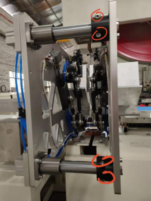
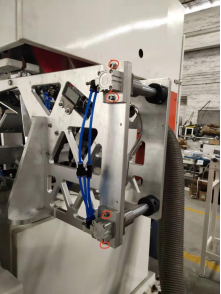
b) Place the main unit and adjust the level first, then loosen the screw in the red circle shown in the photo, and pull the shaft out.
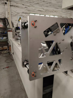
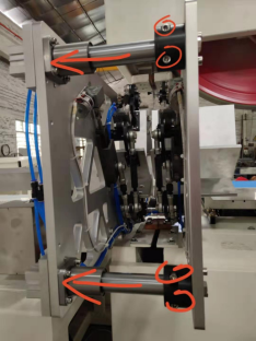
c) Link the band saw part to the 2 screw rods of the host (as shown by the red arrow in the figure below), and adjust the blade of the band saw part to the middle of the mold by adjusting the screw rod.
d) After the installation is completed, perform trial cutting through the manual page and observe the verticality of the cutting. If the cutting is inclined, adjust the screw directly to adjust the angle of the blade. After the cutting is vertical, the screw nut can be locked. (The angle of the blade has been ground before the machine comes out. If the cutting is not vertical when the customer installs the machine, it can be adjusted through the link screw of the host and the band saw.)
2.5 Install
a) After the machine is in place, directly adjust the position of each part with a hoist or organizer;
b) Adjust the level, adjust the anchor screws of each part so that the rollers of the machine are on the same level, and then lock each part with the screws.
C) Assemble the individual parts removed from the factory for shipment;
d) Install the electrical control part; (this machine uses three-phase five-wire power supply, the line voltage is 380V, and the voltage fluctuation is within ±5℅; the resistance of the ground wire cannot be greater than 4 ohms, and the three shorter lines are U, V and W are three-phase, marked with "0" as the zero line (ie, the neutral line of the transformer), and the yellow-green two-color line is the ground line.)
e) Connect the air source to the pneumatic triplet; (see Figure 2-5 for the specific connection method)
Remarks: The assembly, installation and debugging of the equipment are carried out by the personnel of the manufacturer, and the detailed process will not be introduced here.
3 Debugging and Parameter Setting
3.1 Work before debugging
- Read the instructions carefully to understand the working principle of the machine;
- Check whether the wiring is loose, whether the power supply used meets the requirements of the motor, and whether the electrical box is well grounded.
3.2 Operation panel description
The operation panel is divided into left, right and bottom, as shown in Figure 3-3. The left is the touch screen man-machine interface, which can be operated by clicking.
3.3 User interface instructions
This slitting machine system adopts imported brand LS power production programmable controller as the control center of the system. The domestic Xinjie stable man-machine interface is used as a man-machine dialogue and a reliable servo actuator. The above configuration makes the performance of the whole system stable and the cost performance is greatly improved.
The following describes how to operate the machine in detail. Before turning on the power, check the electrical connection between the devices and the safety door and each detection switch, and then turn on the power after confirmation. After power on, the machine will display the following screen:
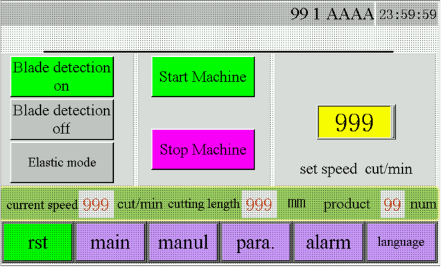
1. Saw blade detection: saw blade detection switch
2. Long distance mode: cutting mode switching
3. Tightening mode: mode switching of clamp clamping
4. Paper cutter operation: operation
5. Paper cutter stops: Stop
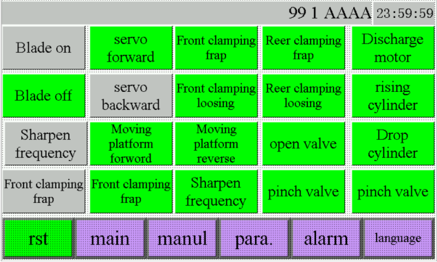
1. Band saw on, band saw off: band saw switch
2. Knife sharpening frequency conversion: knife sharpening motor operation
3. Rear trough lifting, rear trough lowering: platform lifting
4. Servo forward rotation, servo reverse rotation: feeding servo forward and reverse rotation
5. The swing material moves forward and reverse: the platform moves forward and reverse.
6. The left clamp is small and the left clamp is large: adjust the size of the left clamp
7. The right clamp is small and the left clamp is large: adjust the size of the right clamp
8. Knife sharpening: manual sharpening
9. Extension valve: Extension cylinder operates manually
10. Clamping valve: clamping cylinder operates manually
11. Stopper cylinder: The stopper cylinder operates manually
12. Loading cylinder: The loading cylinder operates manually
13. Discharging cylinder: The discharging cylinder operates manually
14. Pressure relief valve: pressure relief of clamp cylinder
Parameter screen:
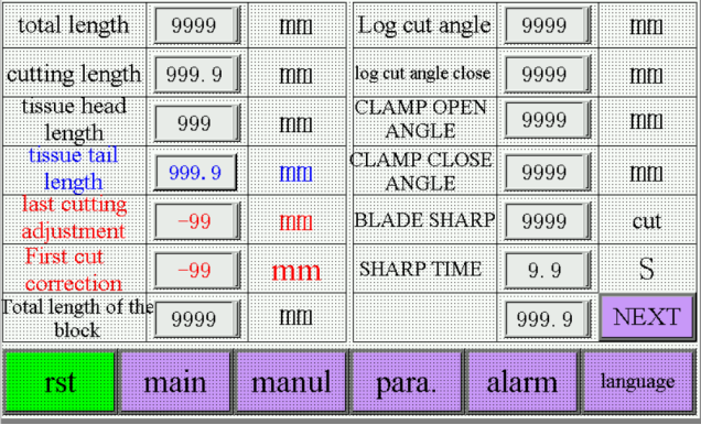
1. Total length of paper roll: raw material length
2. Cutting length: finished product length
3. Head cutting length: head length
4. Tail cut length: Tail length
5. End cut correction: fine-tune correction of the last paper
6. First cut correction: correct the actual and set error of the first cut error.
7. The total length of the push stop: the distance from the origin position of the push paper to the blade
8. Expansion angle: starting position of clamp expansion
9. Closing angle: the end position of the clamp opening
10. Pressure relief angle: starting position of clamp pressure relief
11. Pressure relief closure: end position of clamp pressure relief
12. Number of cuts when sharpening the knife: How many times do you sharpen the knife?
13. Knife sharpening time: the time required to sharpen the knife each time
4 Use and Operation
4.1 Operate
The whole operation process is divided into pre-operation and production operation.
4.1.1 Advance action
a) Adjust the sharpening device: mainly for the adjustment of the sharpness of the tool.
b) Adjust the zero reset of the equipment
4.1.2 Production operation
Put the paper roll into the front conveying trough and run the test machine at low speed for about one minute before speeding up production.
5 Troubleshooting
5.1 Common machine failures and solutions
NO. | Fault | Approach |
1 | Unable to start | Open the air switch |
Turn on the emergency stop switch | ||
Check if the power cord is connected | ||
2 | Reset failed | Check if the zero sensor is normal |
Adjust the zero point sensor to about 5-8 mm distance from the push board | ||
3 | Knife break protection | Check for broken blades |
Adjust the distance from the broken knife sensor to the blade about 5 to 8 mm | ||
4 | Sharpening without sparks | Raise the sharpening screw |
5.2 Waste disposal
Unqualified products caused by debugging should be packed in waste containers in time, and should not be stacked on the machine and work surface, and should not be close to inflammable and explosive materials.
Chapter 6 Safety Protection
6.1 Principles of safety protection
The machine adopts the method of targeting guards.
6.1.1 Targeted protective devices
Targeted protective devices are aimed at the exposed moving parts of the machine, which cannot be completely isolated from the outside world during debugging and operation. Protective covers and protective rods must be installed on the moving parts to prevent the operator's hands or other parts of the body from contacting the moving parts. For injuries, all must be installed when the machine is installed, and must not be removed at any time.
6.2 Safety protection facilities
The targeted protective device of the machine has been installed by the manufacturer, and the detailed location will not be introduced here.
6.3 Noise
The noise of the machine is greater than 60 decibels, so if necessary, protective measures must be taken for those who work in a bright environment for a long time, such as wearing ear protectors.
Warning: Prolonged exposure to loud noise can cause permanent hearing loss or buzzing, mental exhaustion, fainting, loss of balance, or incoherent speech and loss of sound discrimination.
6.4 Fire safety
Before leaving get off work, check whether there are sparks left by sharpening the equipment inside the equipment, and clean up the iron filings, dust, etc. produced by sharpening the knives. After shutting down the equipment, the staff must observe the equipment for 10 minutes without any abnormality, and can only leave work after identifying no sparks and flames.
6.4 General
6.4.1 Installation
The installation of the fully automatic packaging machine must follow the instructions provided by the manufacturer and the safety regulations stipulated by the state.
6.4.2 Machine safety and protection
The machine is equipped with electrical or mechanical safety guards to protect the machine and its operators, and under no circumstances can the safety guards be removed or rendered ineffective.
6.4.3 Inspection, Repair and Maintenance
It is forbidden to perform any inspection, maintenance and repair on moving parts; use obvious warning signs to warn all people to pay attention to possible dangers; before performing inspection, repair and maintenance work, turn off the main power switch to cut off the power supply, and turn off the main power supply. The switch is locked in the OFF position to prevent accidental starting of the machine.
In order to ensure the trouble-free and full-efficiency operation of the machine, first follow the instructions provided by the manufacturer and perform necessary maintenance work; regularly check whether all safety protection facilities are functioning properly; check the condition of the connecting cables, if the cables are damaged, they must be replaced in time.
6.4.4 Electrical system safety rules
- Electrical maintenance and troubleshooting should only be carried out by persons with formal training and expertise;
- Do not modify or omit the protective interlocking device;
- When the power is on or running, please do not get close to the live part or work on it to prevent the occurrence of electric shock;
- When the troubleshooting is confirmed, the power supply must be cut off, and the main switch must be locked;
- Electric cabinet doors must be locked with appropriate warning signs on them;
- Before opening the electric cabinet door or switch panel, the main power switch must be turned off to cut off the power supply;
- Do not modify the circuit unless authorized by the manufacturer;
- When replacing electrical parts, it is necessary to first determine whether they meet the specifications, including the color coding of the wires;
- Do not wear metal glasses, necklaces, etc. when operating electrical equipment; also do not wear rings, watches, bracelets.
6.4.5 Qualified staff
Installation, removal and technical service of the machine must be performed by qualified personnel. Use appropriate tools and equipment and follow the instructions provided for certain tasks.
6.4.6 Deactivation of the machine
If the machine is no longer in use, remove the mains power cord and enable all safety precautions.
Chapter VII Maintenance
7.1 Precautions for maintenance
-Maintenance personnel must have the corresponding professional knowledge in addition to the qualities that operators should have;
- No inspection, repair and maintenance can be performed on moving parts;
- Before any maintenance of the machine, the main power switch must be turned off;
- Regularly check the normal function of all safety protection facilities and the condition of connecting cables, and deal with problems in a timely manner;
- It is forbidden to work on live objects. The door of the electric cabinet should always be locked. If the door of the electric cabinet needs to be opened, the main power switch should be turned off;
- The machine is equipped with an emergency stop button. When an emergency occurs, the emergency stop button should be pressed immediately;
- If the machine is not used for a long time, the main power cord of the machine should be removed, and all safety barriers should be activated;
- Cleaning of the machine can only be started when the machine has been completely stopped.
7.2 Maintenance
a) In order to prolong the service life of the machine, ensure production safety and improve production efficiency, the machine must be regularly maintained as required.
b) a) Every 8 hours of work, the machine must be fully cleaned;
c) b) Every 40 hours of work, oil must be injected into each lubricating point;
d) c) Every 80 hours of work, it is necessary to check whether the fastenings are tight and whether the moving parts move normally;
e) d) Every 80 hours of work, all safety facilities on the machine must be checked to ensure that it is in good condition and effect;
f) e) Every 80 hours of work, it is necessary to check whether the grounding wire is reliable;
g) f) Every 2000 hours of work, the inside of the electric cabinet must be cleaned, and all foreign substances must be removed with a vacuum cleaner. Do not use compressed air to blow or use ether to clean the contacts of the contactor;
h) g) Remove the moisture in the pneumatic triplet at any time;
i) h) Every 6 months of work, the oil must be changed in the place where the oil should be changed, and the oil must be refueled in the place where the oil should be refueled;
j) i) Every 6 months of work, the above inspections must be repeated, and the worn parts must be repaired or replaced;
k) j) Every year of work, major maintenance must be carried out, the bearings that are not running well must be replaced, and the worn parts must be repaired or replaced as necessary;
Chapter VIII Wearing Parts
8.1 List of machine wearing parts
See Table 8-1 for the detailed list of wearing parts of the machine
NO. | Name | Model |
1 | Blade | 5180*100*1.05 |
Chapter 9 Electrical Part
9.1 Electrical schematic
The electrical schematic diagram of the automatic paper cutter is divided into the main circuit schematic diagram and the control circuit schematic diagram, see Figure 9-1 and Figure 9-2
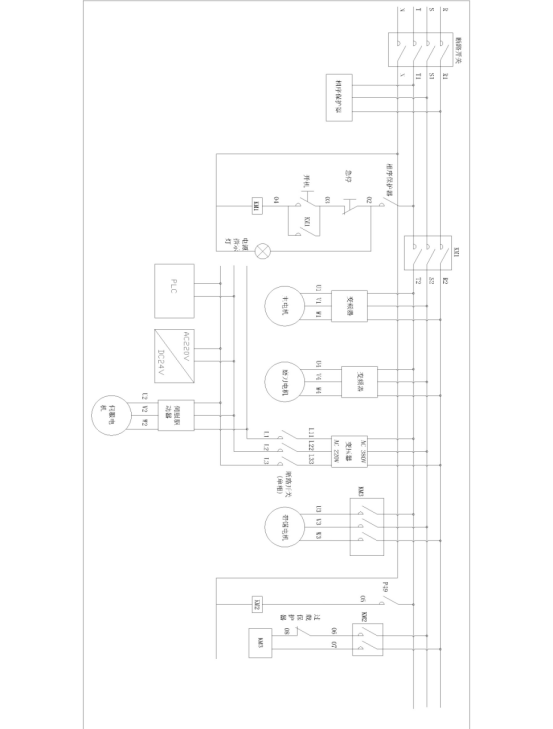
Figure 9-1 Schematic diagram of the main circuit of the automatic paper cutter (1)
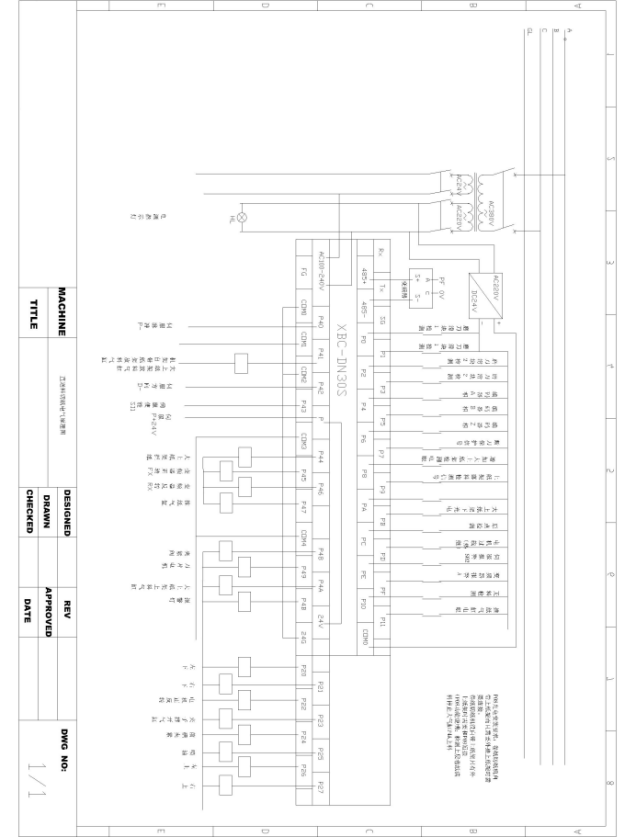
Figure 9-2 Schematic diagram of the control circuit of the automatic paper roll packaging machine
9.2 Summary table of electrical components of electric box
See Table 9-3 for a summary of the electrical components of the automatic paper roll packaging electrical box
NO | Name | Brand | Model | Quantity |
1 | air switch | TENGEN | DZ47-60 | 1 |
5 | relay | Omron | LRE14N | 4 |
6 | PLC | XBC-DN30S | 1 | |
7 | switching power supply | NES-50-24 | 1 | |
8 | Inverter | SV015IG5-4 | 1 | |
9 | AC contactor | TENGEN | LC1-E2510 | 1 |
10 | AC contactor | TENGEN | LC1-E1210 | 2 |
11 | relay | OMRON | 220V | 1 |
12 | server Driver | DS20P0 750W | 1 |
9.3 External power connection
a) Before wiring, it must be confirmed that the electrical control equipment and rated voltage of the machine match the supply voltage of the AC power supply;
b) The power cord is divided into L1, L2, L3, PE grounding wire, and the wiring of the power supply must be verified correctly before starting the machine.
9.4 Power Requirements
a) 3-phase 380V, 50Hz industrial power supply, external power supply connection, using delta connection.
9.5 Power Check
a) Before checking the power supply, disconnect the input power and wait at least 10 minutes before starting to check the electrical equipment. At the same time, make sure that the charging indicator light of the inverter has been turned off, otherwise it will lead to the danger of electric shock.
b) Power inspection must be carried out by competent personnel for maintenance, inspection and parts replacement.
c) The electrician should tighten the terminal screws regularly. Loose terminal screws may cause overheating or fire.
d) Regularly check all electrical equipment of the motor and the temperature rise.
10 Sharpening Operation
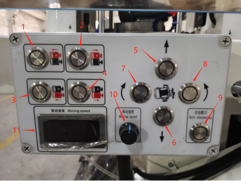
Button 1: Separately adjust the upper grinding wheel to reduce the grinding cut.
No. 2 button: separate adjustment of the upper grinding wheel to increase the grinding.
Button 3: Adjust the grinding wheel to reduce the reduction separately.
Button 4: Grinding wheel is increased under separate adjustment.
Button No. 5: Move the upper and lower grinding wheels forward (subject to the direction in which the button is operated by the person).
Button No. 6: The upper and lower grinding wheels are backward (subject to the direction of the human operation button).
Button 7: The angle between the upper grinding wheel and the blade decreases, and the angle between the lower grinding wheel and the blade increases.
Button 8: The angle between the upper grinding wheel and the blade increases, and the angle between the lower grinding wheel and the blade decreases.
Button 9: The switch of automatic sharpening, after turning on the grinding wheel will automatically feed the grinding wheel according to the grinding degree of the blade.
Knob 10: Adjust the movement speed of the appeal button, generally adjusted to 20~30. No. 11: The speed of the knob 10 is displayed on the screen.
11 Hydraulic System
1: Hydraulic gauge, showing the current blade tensioning pressure.
2: Pressure relief handle, turn the hydraulic lever to the right to extend the blade for tensioning, and loosen the hydraulic lever to the left to lower the blade to loosen.
3: Air pressure switch, the hydraulic system is powered by compressed air.
4: # 46 Hydraulic oil filling port.
If you have any corrections, please call the company or visit the company's website, thank you very much
Notice!!!
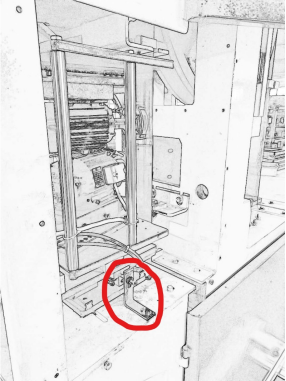
This is part is fixed for protect the motor when transport the machine
Please Take Out this part before you run the machine(Please see the part in cycle)!!
By continuing to use the site you agree to our privacy policy.